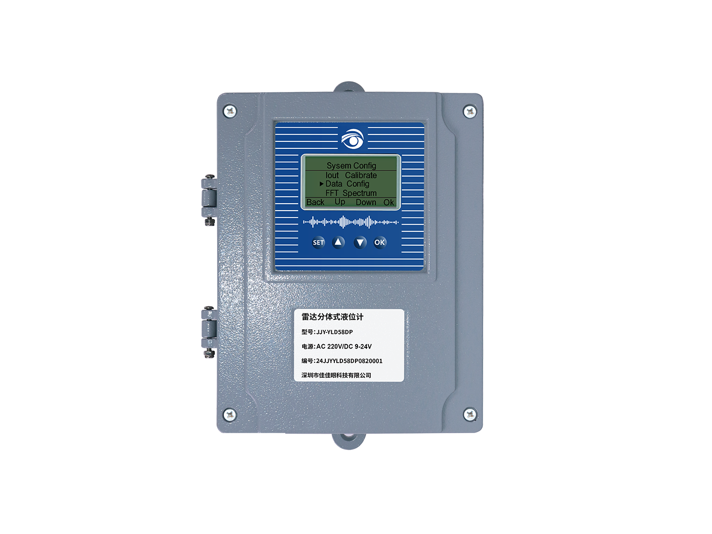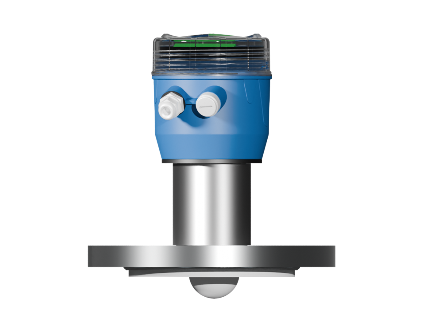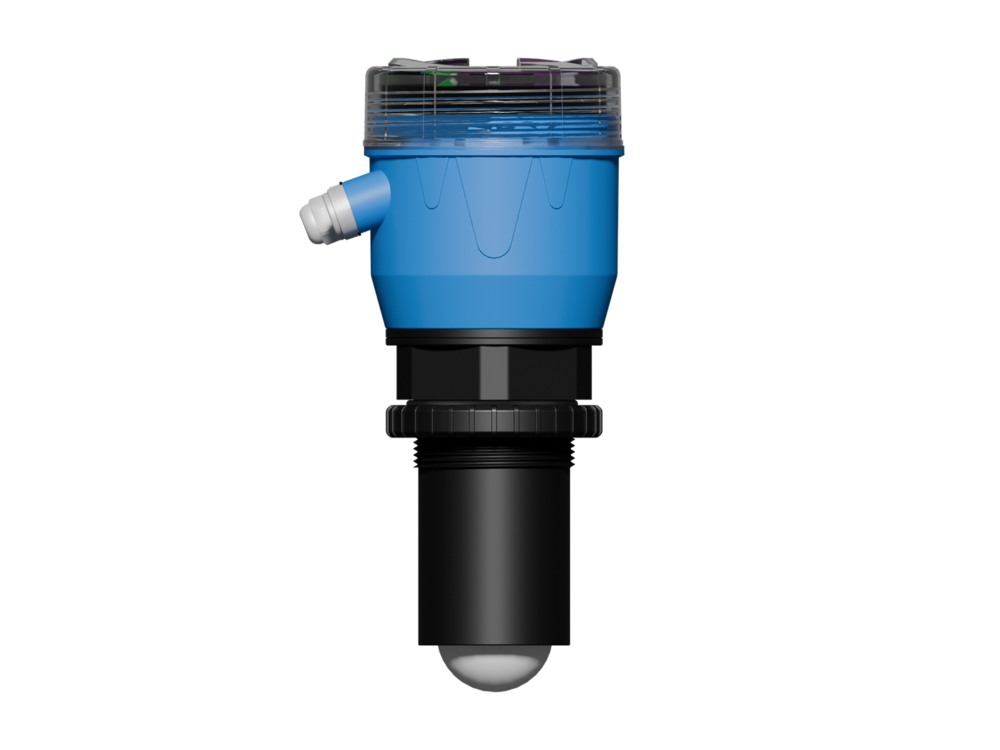
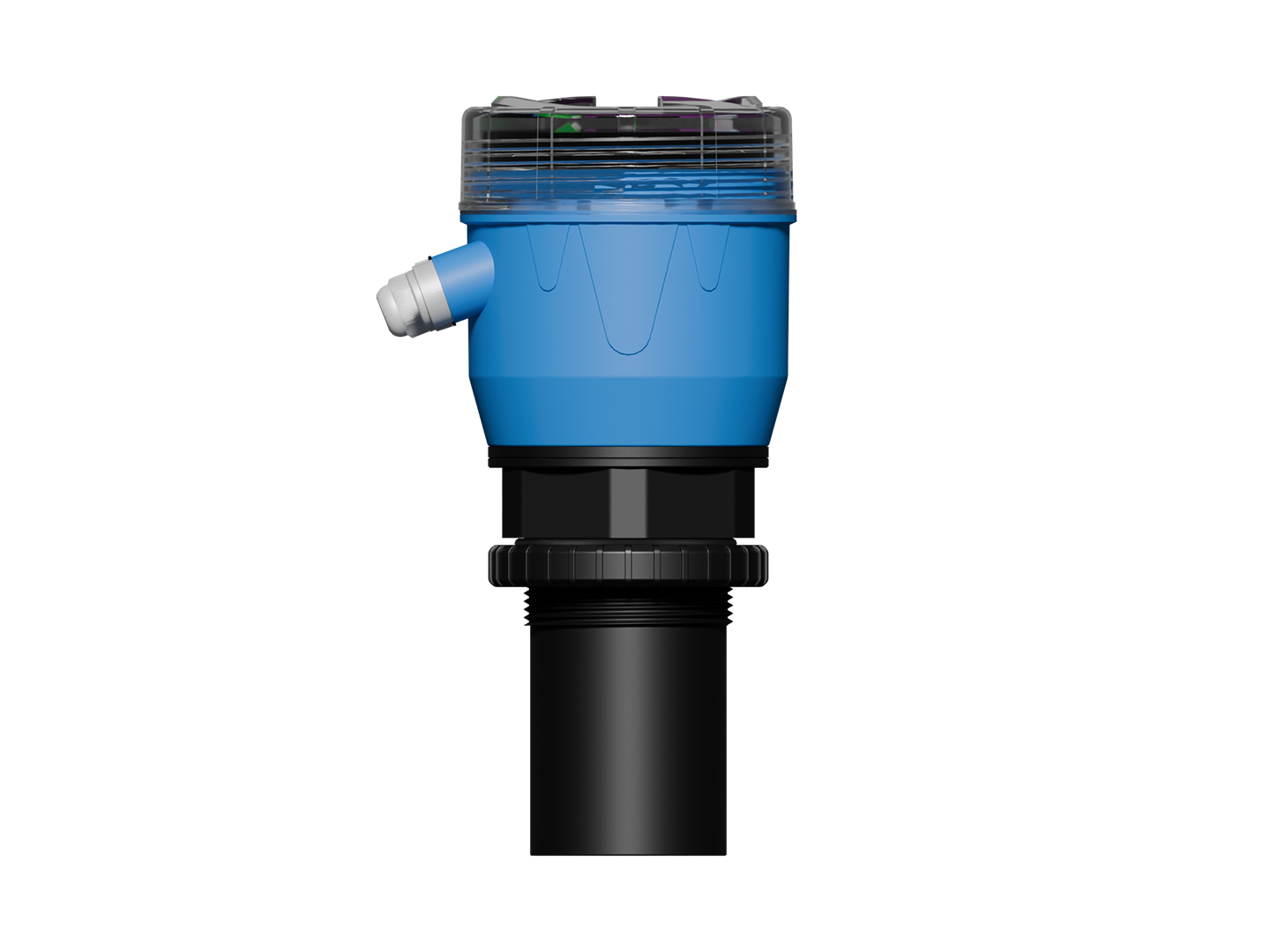
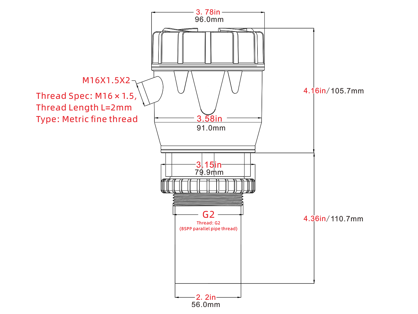
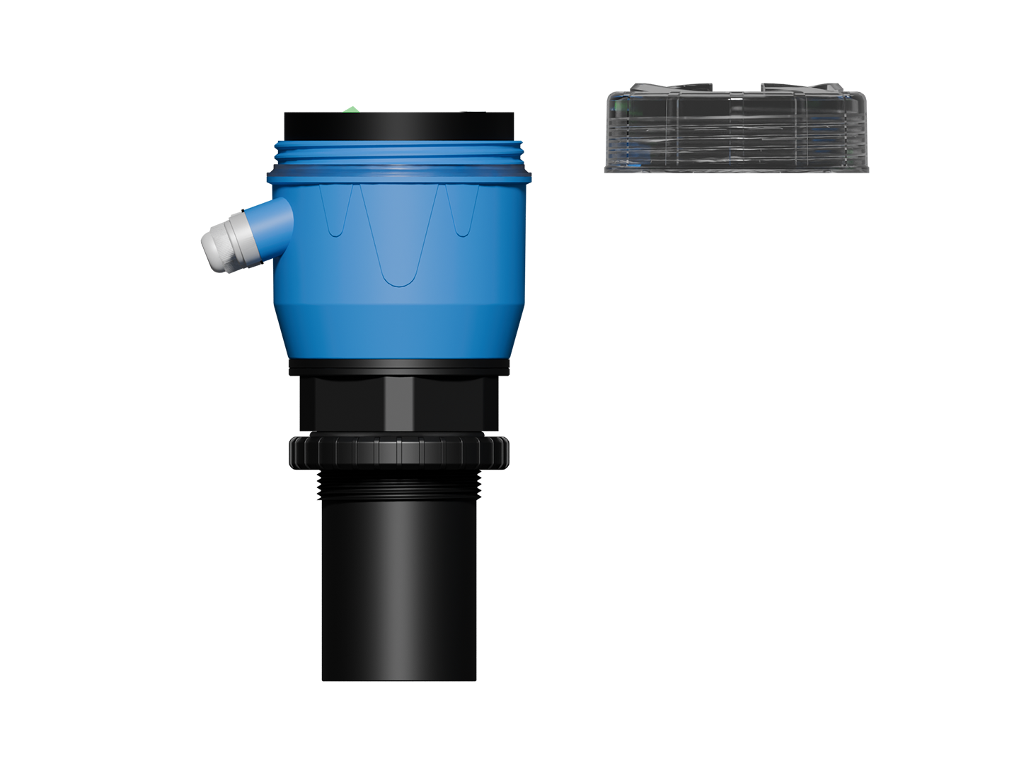
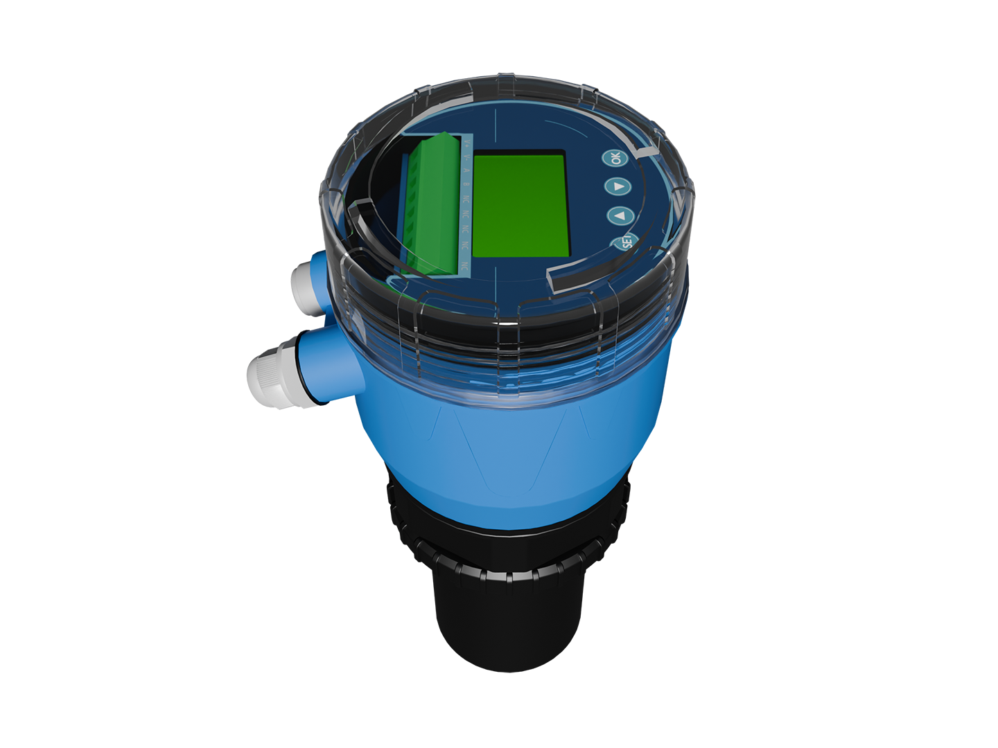
| Model | JJY-YCD238SPY |
|---|---|
| Communication Mode | 4-20mA Two-Wire / RS485 |
| Operating Current | 58mA instantaneous current at power-on |
| Measurement Accuracy | ±2mm |
| Operating Temperature | Display: -20°C ~ 70°C; Sensor: -40°C ~ 80°C |
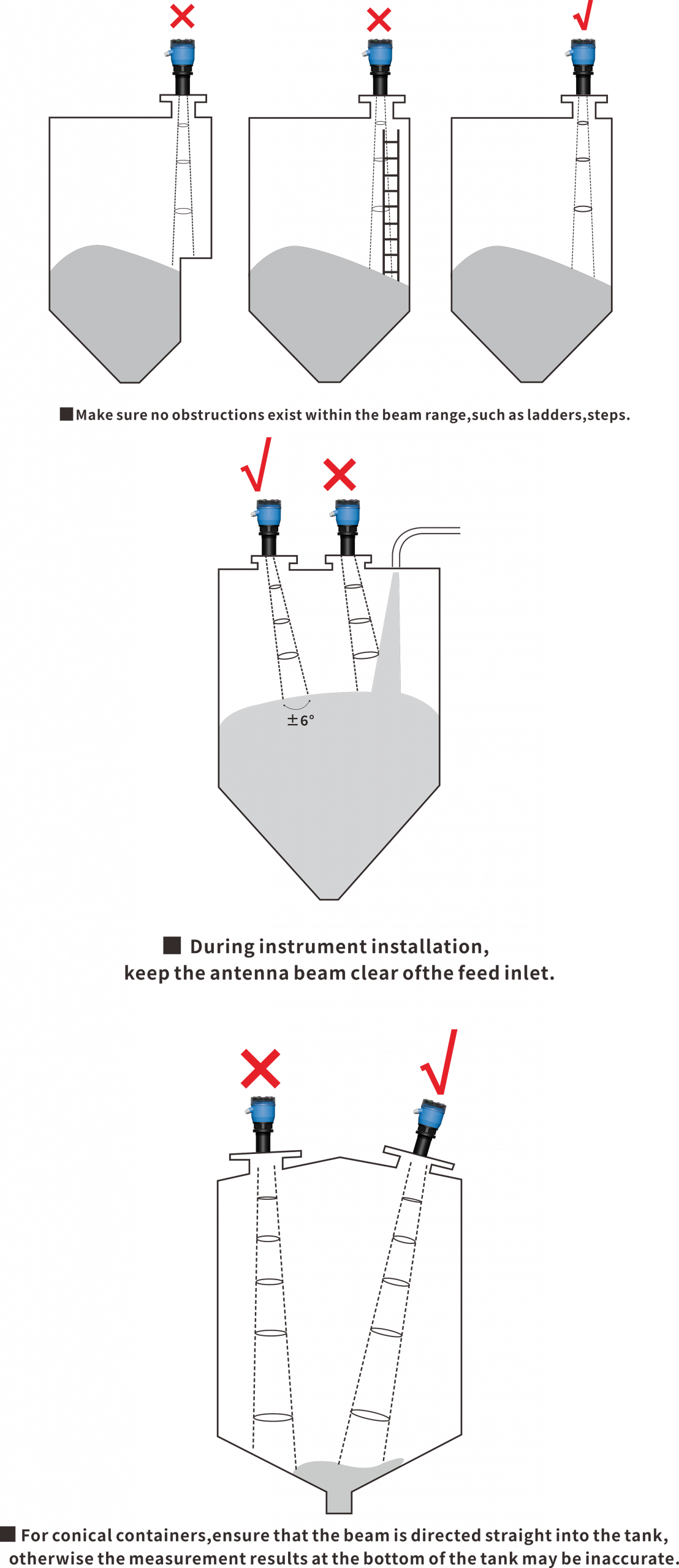
| Beam Angle | ±6° |
| Measuring Range | 0.05m ~ 20m |
| Sampling Frequency | 1500ms, configurable |
| Temperature Display | Supported |
| Display Mode | Chinese & English display with backlight |
| Housing Material | PC |
| Display Backlight | Supported |
| Mounting Thread | G2 |
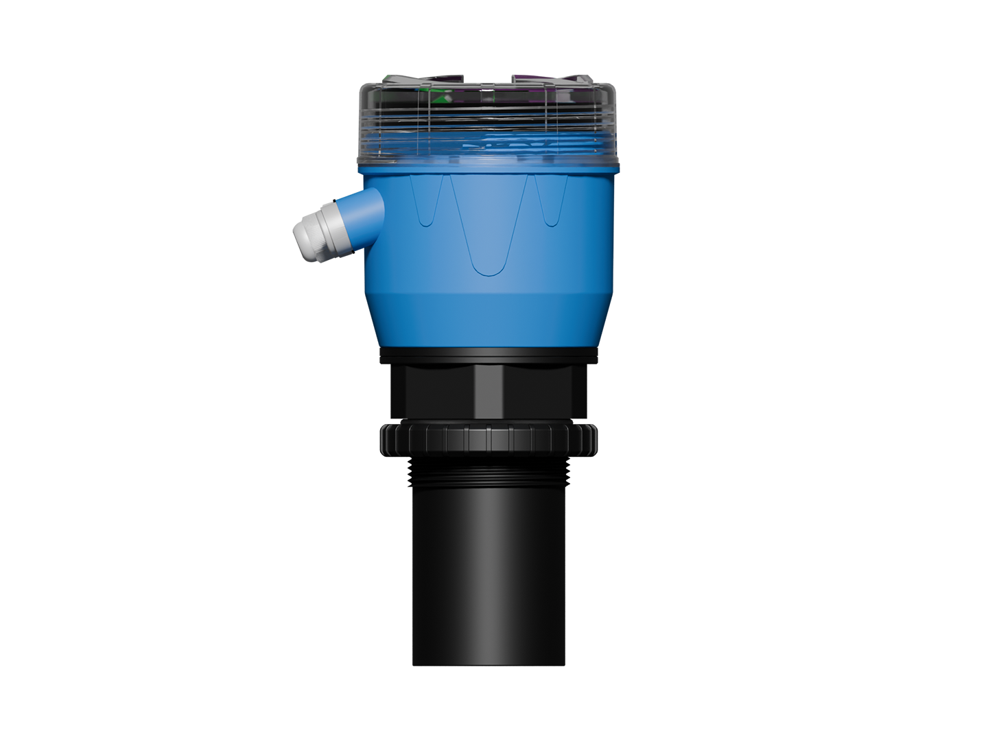
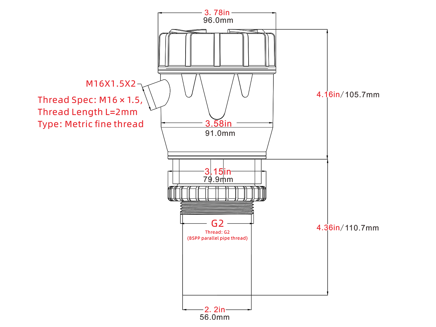
Integrated Ultrasonic Level Meter
| Parameter | Value |
| Measuring Range | 0.05 ~ 15 m |
| Accuracy | ±2 mm |
| Blind Zone (Dead Band) | 5 cm |
| Beam Angle | ±6° |
| Signal Output | 4–20 mA / RS485 (switchable) |
| Two-wire power supply | DC 22 ~ 26 V |
| 485 power supply | DC9~26V |
| Display Operating Temperature | -10 °C ~ 70 °C |
| Device Operating Temperature | -40 °C ~ 70 °C |
| Acquisition Frequency (2-wire) | 1500 ms / configurable |
| Acquisition Frequency (RS485) | 200 ms / configurable |
| Housing Material | PC (Polycarbonate) |
| Temperature Detection Range | -70 °C ~ 150 °C |
| Screen Backlight | Supported |
| Protection Rating | IP67 |
| Communication Protocol | Modbus |
| Button | Function on Main Screen | Function in Settings Screen | Description |
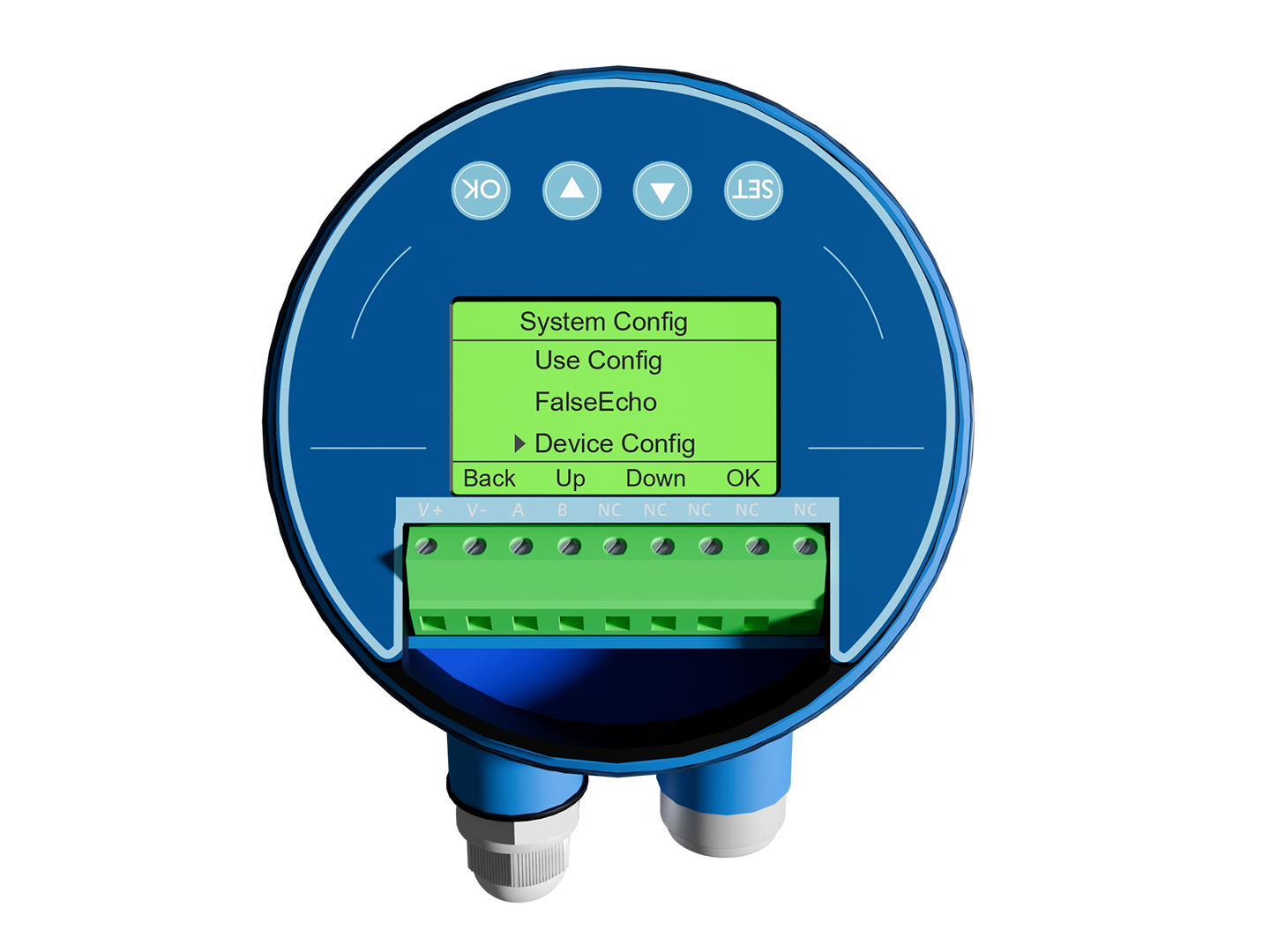
| SET | Enter system settings | Return to previous level | Long-press or short-press to enter menus; navigate back step by step |
| ▲ / Up | Enter system settings | Move up / increase value | Increment the current selection or numeric value |
| ▼ / Down | Enter system settings | Move down / decrease value | Decrement the current selection or numeric value |
| OK | Enter system settings | Confirm / enter sub-menu | Confirm a selection or open the highlighted sub-menu |
4.1 4–20 mA Two-Wire Connection
| DC 22-26V+
Power+/Signal+
|
→ |
V+ |
| DC 22-26V-
Power-/Signal-
|
→ |
V- |
Power supply doubles as signal output. 4 mA corresponds to the low point of the measuring range; 20 mA corresponds to the high point.
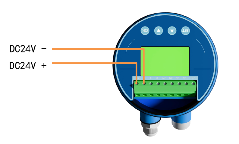
Figure 1 — Wiring diagram for 4–20 mA two-wire connection
4.2 RS485 Communication
| DC9-26V+ | → | V+ |
| DC9-26V- | → | V- |
| 485-A | → | A |
| 485-B | → | B |
Default address code: 127. Default baud rate: 9600. Protocol: Modbus.
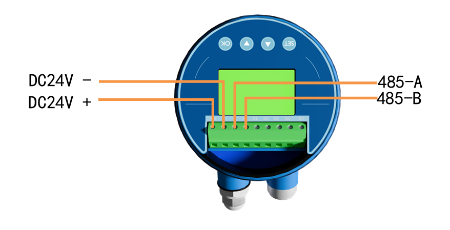
Figure 2 — Wiring diagram for RS485 communication
⚠ Recommended cable outer diameter: 4 – 8 mm. After power-on, the screen lights up, indicating that the supply is normal.
Step 1 — Power-on confirmation
Power-on Check: For 4-20mA mode, connect a DC 22–26 V power supply; for RS-485 mode, connect DC 9–26 V. A lit screen displaying the menu interface indicates a successful power-on.
⚠ After power-on, use a multimeter to verify that the supply voltage is between 22 V and 26 V. If the measured voltage is slightly below 22 V, turn off the screen backlight to reduce operating current and avoid inaccurate current output caused by under-voltage.
Step 2 — Set the installation height or installation water depth (choose one)
Press SET → select “Level Configuration” → press OK → choose “Installation Height” or “Installation Water Depth”.
Enter the value and press OK to save.
Step 3 — Return to the main screen
Press SET to return step by step. The main screen now shows the real-time level / material level value. Setup is complete.
| Requirement | Menu Path |
| Switch installation mode | Application Configuration → Installation Mode → Normal / Suspended |
| 4–20 mA calibration | Calibration Configuration → Current Calibration → 4 mA / 20 mA |
| 4–20 mA range mapping | Calibration Configuration → Parameter Configuration → 4 mA Corresponds To / 20 mA Corresponds To |
| Switch signal output | Output Signal → RS485 / 4–20 mA |
| RS485 parameter setting | Configuration → Address Code / Baud Rate |
| Data fluctuation is large | Data Smoothing → Change Range + Duration + Sliding-window Filter |
| Weak echo energy | Application Configuration → Power Adjustment → Adjust to level 2–5 |
| Multiple echoes in confined space | Application Configuration → Application Algorithm → Select Nearest Frequency Point |
| Language switch | Device Configuration → System Language → Chinese / English |
| Restore current to factory default | Calibration Configuration → Restore Default → Confirm |
| Screen backlight | Device Configuration → Screen Backlight → On / Off |
| Blind Zone Setting | Application Configuration → Installation Mode → Microwave Blind Zone |
Suspended (hanging) installation:
Directly masks the area approximately 20 cm below the probe. Suitable for installations in open environments.
Normal installation:
Designed for scenarios where the material/water level may rise and become very close to, or even contact, the radar antenna — for example, material silos, tanks, etc.
| Symptom | Possible Cause and Action |
| Screen does not light up | Use a multimeter to check whether the voltage is within the 9–26 V range. |
| Value does not change or jumps erratically | 1) Check whether the installation is vertical. 2) Confirm that the measured surface is outside the blind zone (5 cm). 3) Go to “Data Smoothing” and appropriately increase the Change Range (e.g. 15 cm) and Duration (e.g. 30 s), and enable the Sliding-window Filter (e.g. 30). |
| Displays blind zone or weak echo | There may be false echoes (tank walls, obstacles). Adjust the installation position; go to “Application Configuration” → “Application Algorithm” → enable Nearest Frequency Point. |
| Measured value is significantly too large | Go to “Calibration Configuration” → “Current Calibration” and use a precision ammeter to calibrate the 4 mA and 20 mA points. |
| RS485 communication failure | Check whether the A/B wires are reversed; confirm that the baud rate matches the host computer; check that the output signal is set to RS485 mode. |
| 4–20 mA output is inaccurate | Go to “Calibration Configuration” → “Current Calibration” and use a precision ammeter to calibrate the 4 mA and 20 mA points.Use a multimeter to check whether the device’s supply voltage is within 22–26 V. |
⚠ The supply voltage MUST NOT exceed DC 26 V. Using AC mains power is strictly prohibited.
⚠ Always disconnect the power before wiring and installation.
Related Resource Downloads
 |
 |
 |
 |
 |
 |
Copyright @ 2026 Shenzhen Jiajia Eye Technology Co., Ltd.